|
X-150 - A Micro Turbojet Engine Watch me build my engine from scratch !
|
Diffuser and Front Cover |
|
|
Picture |
Description |
 |
This part will be made by CNC machining. How nice if it could be cast then the cost would be so much lowered. Diffuser must work in collaborate with the compressor wheel. Al-Zn alloy 7075 the best material for making it. |
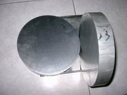 |
Round stock for CNC machining. |
 |
We don't need to have this part machined by brute force, instead we want it be done elegantly. CNC mill machine is about twice as expensive as that of CNC lathe, the service price is about the same situation. Besides CNC turning is much quicker than CNC milling for a axial symmetric part. Diffuser, has a geometry of mostly axial symmetric, so we have better to take the advantage of the lathe, ie, put the round stock on a lathe for quick turning the axial symmetric shape, then move to a mill for machining the rest. Nice idea, isn't it ? |
 |
Engineering change. I have decided not to involve any CNC milling to this part, instead, only CNC turning will be used. 22 Slits will be cut at the rim to allow vanes to slide into then welded. When cutting those slits, 4 axis milling machine will be needed, but I think I didn't make wrong decision as slitting is much faster than milling. |
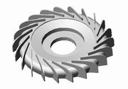 |
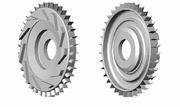
3D rendering of this new diffuser design. This is again the philosophy of design for manufacturing. Blanking those vanes is of course cheaper than 3 axis milling but how about the performance ? well let's see. |
|
|
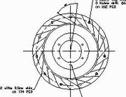
10 layers of 2.0mm thick aluminum sheet are stacked together and guess what ? waterjet will be used again for blanking. In this case 80 pcs of diffuser vanes can be obtained. There are many other options for cutting such as laser cutting, all up to your decision. |
 |
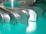
Vanes obtained after blanking. Notice that rolled aluminum sheet is strong in one direction only, so when blanking keep the longitudinal direction of these vanes perpendicular to its weak axis, this helps withstanding the bending moments from pressurized air stream. |
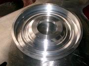 |
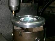
Diffuser disk in process of CNC turning. This side exposes to radiation heat from the combustion chamber, i.e., hot side. |
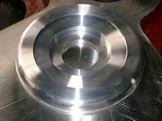 |
Diffuser disk in process of CNC turning. Viewed from the front side, where the compressor sits. This work piece is almost done except two cuts are needed at the rim to finish the job, i.e., one rough cut, one finishing cut. |
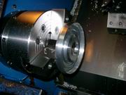 |
Finishing cut of diffuser disk. Click on the picture to see the video clip of the very last step of turning. Really elegant and fast using lathe to do the job. |
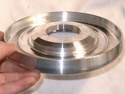 |
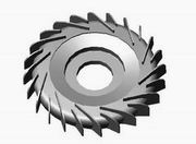
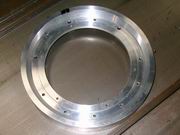
CNC turning completed. She's really gorgeous, isn't she ? Not yet ready, to put the diffuser to work there are some processes needed such as drilling, taping and slitting, TIG welding. |
 |
Drilling the diffuser disk. A DRO is installed in this drilling machine, so precision holes can be obtained. |
 |
Cutting the slots for vanes. The noise generated is deafening loud even you're 5m away it still can be comparable to that of a pulsejet engine. The cutter is in low speed like a hammer hits the disk triggered the ringing mode of it. Believe me, in this case using hands as hearing protection device (folding your ears, or plugging with fingers) is inadequate. Click on the picture to see the video clip. Take it easy, no audio is included. |
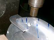 |
I was kind of nervous when tried
fitting the vane to the slot. If anything went wrong the disk might have to
be abandoned so check the slitting work step by step. Phew ! it looks OK.
What machine I am using ? Well, nothing but an ordinary 3 axis manual mill with DRO, attached with an index head on the table to provide the 4th axis , that's it. :-) |
 |
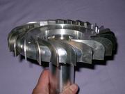
Put together the disk and vanes. Not yet TIG welded. |
 |
Close up view of diffuser. |
 |
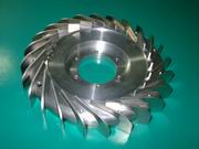
Completed diffuser. TIG welded. Yes it is air tight between front side and back side, so compressed air is guided along the tunnel into the combustion chamber. When welding make sure not to input too much heat, or it tends to rupture or gets distorted, i.e. jump here and there and cool down the work piece from time to time. |
 |
Here comes another engineering change. I will cut some of the vanes shorter to prevent surging. Thanks to my UK friend who advised me on the number of vanes. |
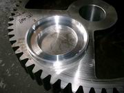 |
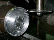
Front cover work piece in process. CNC lathe is used to turn this part. Background is a giant spur gear, I don't know what machine it will be served, but it is in heavy industry category for sure. |
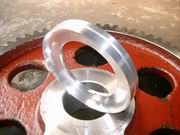 |
Front cover. CNC turning process is done. It will be sent to next stop for drilling and taping. Viewed from the rear, i.e., "Business end" in contact with diffuser. |
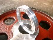 |
Front cover. Viewed from the front, i.e., this end is in contact with intake. |
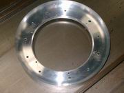 |
Axial holes of front cover have been drilled. Viewed from the back. |
 |
Axial holes of front cover have been drilled. Viewed from the front. |