X-150 - A Micro Turbojet Engine
Watch me build my engine from scratch !
| Back | Next |
|
X-150 - A Micro Turbojet Engine Watch me build my engine from scratch !
|
Test Stand |
|
Picture |
Description |
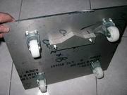 |
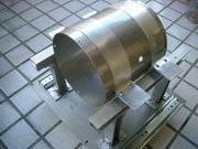
With some scribbling, the bottom of this test stand looks like belly of a turtle. Yes, this turtle will be used to carry on its back a special guest, our X-150, and measure how much thrust our engine can generate. I don't use kitchen scale, instead I use load cell to measure the thrust. The subsequent turbofan and turboprop engines will all use this test stand, let's put the capacity of the load cell to say 300kgs. The thrust will be exerted on the load cell through the hump like pusher, which is a leftover material of my balancer subproject. :) |
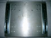 |
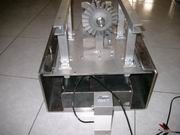
Linear bearings installed on top face. When holding both bearings down the test stand will not be able to go up or pitching while still allow moving back and forth freely. |
 |
Engine lugs made of aluminum sheet. When into mass production stainless sheet will be used instead, and offering higher strength. We need four legs to support these lugs and fasten them to the test stand, but legs are still missing. As to these legs I'll go to the material shop for some extrusion bars but the shop told me that they won't be operational until next Monday. Well, happy lunar new-year ! |
 |
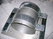
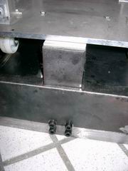
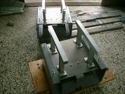
Engine support frame under construction. Need bracings to strengthen shear strength. Now you understand why we need the linear bearings to hold down the test stand, because engine is exerting thrust at a elevation, on the base plate there will be a moment acting, forcing the test stand to go pitching. |
 |
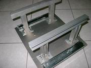
Support frame completed. The test stand now weighs more than 5kg,and is very strong. A base frame for mounting load cell is still missing. |
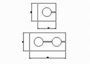 |
Here comes the question : which type of load cell will be better, one hole or two hole ? The answer is very simple, it depends on what resolution we'd like to have. Obviously two hole will be more sensitive than one hole. For two hole cell, under the same change in loading you have relatively larger delta strain readings than that of one hole cell. |
 |
This is a brand new load cell. Beam type, capacity 300kgs, ready for use. After been delayed by the lunar new-year holidays for two weeks, I have decided to accelerate the progress of my project so I'll use load cells off the shelf directly. If I have time I'll fabricate the load cell all by myself but not much money can be saved. As for the thrust indicator, I chose to build it because I'd like all the data from the engine can be displayed on the same control panel, and any PC with an A/D card can do the job. |
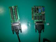 |
The AD/DA converter. A/D 8 channels, D/A 2 channels. Now we have enough channels for monitoring thrust, TIT, EGT, Oil pressure, CDP (Compressor Discharge Pressure), fuel flow rate, rpm, etc. and still have 1 unused A/D channel and 2 D/A channels. |
 |
A TIG welder is working on the base frame of my test stand. |
 |
This is the test stand assembly. Base frame, load cell, upper frame are all put together. Load cell not yet mounted. This completed test stand now weighs more than 40kgs. |
 |
Closer up view of the load cell being mounted. Load cell is protected by a 8mm thick carbon steel plate. Well all set, this test stand is ready for use ! |
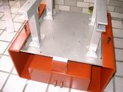 |
A little painting for rust proof. This is going to be a mobile thrust stand, I'll carry it to any air show for demonstration. |
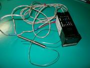 |
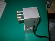
Omron temperature controller + K-type thermocouple I bought from the internet. K-type thermocouple will be mounted at where TIT should measure, but the controller will be replaced by ECU. |
 |
These are updated version of our test stand. It can be used to test engines of thrust from a few pounds to 200 pounds. |