X-150 - A Micro Turbojet Engine
Watch me build my engine from scratch !
| Back | Next |
|
X-150 - A Micro Turbojet Engine Watch me build my engine from scratch !
|
Planetary Gearbox |
|
Picture |
Description |
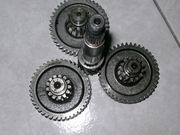 |
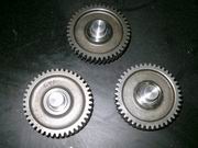
A good planetary gearbox is essential for turboprop engine. After a thorough research into internet, I came to this conclusion that no factory products for my need are available so I must build my own. Retrofitting used gears to build the prototype would be a great choice because they are easily available from eBay or other popular online marketplaces. However not all parts can be bought from internet, ring gear is the one for example. After the design is validated all the gears will be mass produced from blanks. Picture shows all the used parts I got for building the gearbox. |
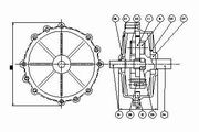 |
Planetary gearbox assembly plot. The reduction ratio of this gearbox is : 1+99/15 = 7.6, where 15 is the number of tooth for sun gear, and 99 is the number of tooth for ring gear. Use differential type if larger reduction ratio is needed. Here's the building plan : 1. cast aluminum housing(2 halves needed) then turn/drill/tap; 2. turn/drill/tap output shaft; 3. turn/mill p-gear retainer; 4. retrofit p-gear by turning away the unneeded pinion; 5. input shaft will be used as-is, no modification needed; 6. cut ring gear; 7. source lock pins and bolts, bearings etc. |
|
|
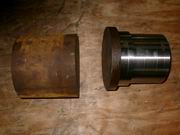
Rusty round stocks for turning retainer and output shaft. You might dispute that output shaft should be turned from casting of similar shape, rather than from such big diameter of blank. Yes, to save material and machining time, casting is the better way for preparing it, but please remember this holds for mass production only, for prototyping, to skip one process usually means both more time and cost effective. So this time we chose to use directly the round stock for convenience. |
 |
Shaft work in progress. Actually the left part of this shaft is another half of the retainer, this is reason why we need to turn such a big bar. Phew ! still a long way to go, a lot of material need to be removed...I swear I'll cast the blank to shape, next time. |
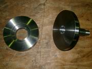 |
Lathe turning of retainer and shaft completed. Retainer on the left, shaft on the right. |
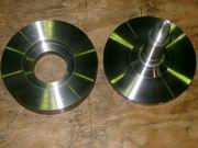 |
Lathe turning of retainer and shaft completed. Shaft is viewed from the back. |
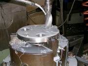 |
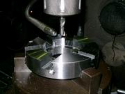
Reaming the bearing seat of output shaft. The work piece is secured on an index head. Click on the picture to see the video clip. |
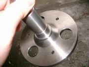 |
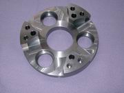
Drilling/milling work of output shaft completed. Viewed from the rear. |
 |
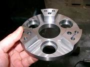
Drilling/milling work of output shaft completed. Viewed from the front. From this side you see four bearing seats and 6 lock pin holes, 3 bolt holes. |
 |
Milling work of retainer. Work piece is secured on an index head, and using end mill tool to do the work. |
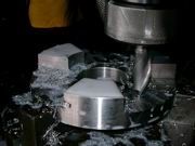 |
Retainer work piece, milling work is still proceeding. |
 |
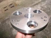
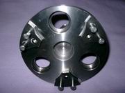
Retainer work piece, bearing seat completed, holes drilled, but gear housing is still not completed. |
 |
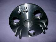
Retainer completed. Gear housing is turned. In this case 4-jaw chuck is needed. |
 |
Engineering change No.1. After calculation, these gears unfortunately have to be abandoned due to strength concern. I need bigger gears for transmitting large torque. So new gears will be cut with larger tooth width. gear housing will be changed in accordance. |
 |
Shaft with lock pin inserted. These lock pin holes were drilled with very high position accuracy, so when assembling the other half, it won't get into trouble matching. |
|
|
I need some extra space for housing bigger planetary gears, so 3 spacers out of 6mm SS41 plate are laser cut. Laser cut holes are accurate in position but the surface finishing is not so good. Use drill to remove the burrs. |
 |
3 spacers are assembled onto disk of output shaft. when pushing the spacers in place, it is really nice and easy, fits perfectly. |
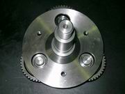 |
Well the gear + shaft assembly looks almost like this. Bearings are still missing. |