X-150 - A Micro Turbojet Engine
Watch me build my engine from scratch !
| Back | Next |
|
X-150 - A Micro Turbojet Engine Watch me build my engine from scratch !
|
The Assembly |
|
Picture |
Description |
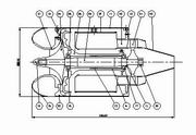 |
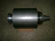
This is the assembly of X-150, 202mm Dia. x 418mm Length. |
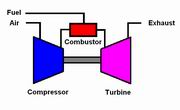 |
Flow diagram of X-150 |
 |
Assembly rear view. In this picture NGV and diffuser and some small parts are still missing. |
 |
Assembly front view. |
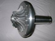 |
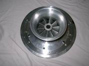
Subassembly compressor + diffuser + shaft tunnel, front view. A little tight between compressor and diffuser, need some adjustment. Diffuser slits for mounting vanes not yet cut. |
 |
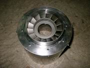
Subassembly compressor + diffuser + shaft tunnel, rear view. |
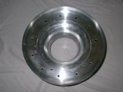 |
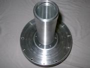
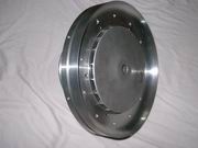
Subassembly intake + front cover, rear view. |
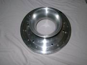 |
Subassembly intake + front cover, front view. |
 |
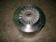
Subassembly intake + front cover + compressor, rear view. |
 |
Subassembly intake + front cover + compressor, front view. |
 |
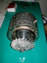
Subassembly outer casing + rear case + NGV, all secured. |
 |
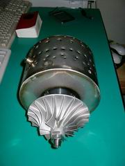
Subassembly outer casing + rear case + NGV + turbine wheel. |
 |
Finally, a subassembly very close to assembly :-) |
 |
Finally, now we can turn the shaft
freely.
Click on the following link to see the video clips : |
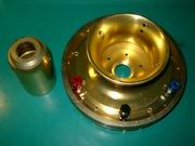 |
Machined Aluminum parts after
anodizing. I do not worship gold, golden is not my favorite color, but it
seems golden color best fit our engine. They could be anodized to customers'
favorite color, if the color is available in the factory.
The blue connector is for fuel, black for lube oil, and red for gas. If gas is not used (for H150B engine, it equipped with direct kerosene starter, so gas connector is not used), the red connector is for measuring P2 pressure. |
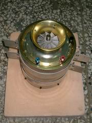 |
With new combustion chamber, new fuel
line, new lube line, I've got this engine assembled. This engine will be put to test in a few days. |
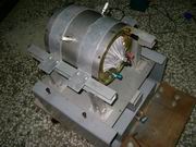 |
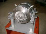
I mounted the engine on the test-stand for further assembly works. |